- The Experiment -
- Experimental method
- Preliminary results obtained with a test setup
- The VIP Experimental Setup
- The CCD Detector
- DAQ, Slow Control and Monitoring
Experimental method
Experimental tests of the Pauli Exclusion Principle for electrons are done, basically, in two different ways:
- the search for the so-called non-Paulian atoms, as the paronic helium for example, characterized by an electron in the fundamental level and another one in an excited one, such as the spin and the space components of the wave functions are both antisymmetric, resulting in a global state of the 1s2s1S0 for which the total wave function is symmetric violation of the symmetrization principle [33];
- the search for anomalous X-ray transitions, i.e. electron transitions to states already occupied by the maximum allowed number of electrons compatible with the Pauli exclusion principle.
It is this second method, already used by Ramberg and Snow [2], and derived from the original experiment of Goldhaber and Goldhaber [42], which will be used in VIP.
The basic idea is to introduce new (fresh) electrons in a copper bar (new in the sense that the already existing ones in the copper bar had already all the time to perform the allowed and prohibited transitions) and measure the K-series (2p->1s) X-ray transitions for which the 1s level is already occupied by 2 electrons. Such transitions, obviously, would only be possible if the Pauli principle is violated, see Fig. 1.
n=2
n=1 |
n=2
n=1 |

Fig. 1: 2p->1s allowed transition 2p->1s transitions violating the Pauli principle
The anomalous transitions are detected by their energy shift because instead of the normal 8.05 keV energy of the 2p->1s transition in Copper, one gets a value closer to the one corresponding to a (Z-1) atom ( 7.5 keV in this case) [43], which can be readily measured (a high resolution X-ray detector).
In order to quantify the proposed VIP improvements in sensitivity, lets briefly discuss the parameters of the Ramberg and Snows experiment [2].
The experimental setup (Fig. 2) used as X-ray detector a proportional chamber, with an energy resolution of about 1200 eV of FWHM at 7 keV, placed above a copper bar in which a current of 30-40 A was circulated. The setup was installed in the basement of Muon building at Fermilab.

Fig. 2: The scheme of the experimental setup used in the Ramberg and Snow [2] measurement
The measurement lasted 2 months, during which data with and without (representing the background) circulating current were taken.
The obtained spectra are shown in Fig. 3.
 |
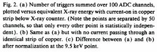 |
Fig. 3: The spectra measured by Ramberg and Snow [2].
Table1: Expected number of X-rays violating the Pauli principle.
Number of new electrons: |
|
Number of scatters just below (in front of) the detector: |
|
Capture probability: |
> (1/10) scattering probability |
Useful solid angle: |
|
Fraction of visible current: |
|
Expected number of X-rays: |
|
Taking into account the integrated circulated current, the geometry and the material characteristics, reported in Table 1, the result of the measurement, in terms of the b-parameter (see Section 1), yielded an upper limit for the probability of the Pauli principle violation of:

Preliminary results obtained with a test setup
A feasibility measurement, applying the same method of Ramberg and Snow, was performed in 1998 for a period of three months, in the basement of the Neuchatel laboratory [44]. The setup used 3 CCDs (Charge-Coupled Device) as X-ray detectors, with an energy resolution of 400-500 eV FWHM, already about 3 times better that the Ramberg and Snow setup.
The total measurement time was of 1856 hours:
- 1524 hours with a circulating current of 5, 10 or 15 A;
- 332 hours without current to measure the background.
In Figs. 4 and 5 details of the setup are shown.
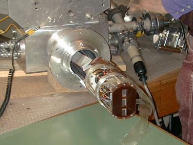
Fig.4: The test setup used at Neuchatel detail of the CCD detectors.

Fig 5: The test setup used at Neuchatel detail on the copper bar.
The measured spectra for one CCD as an example are shown in Fig. 6.
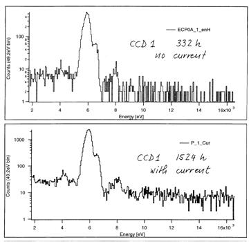
Fig. 6: The measured spectra with the test setup at Neuchatel.
With the improved detector resolution and geometry, taking into account the integrated circulated current, the geometry and the material characteristics, an upper limit of:

was obtained, an order of magnitude better than the Ramberg and Snow measurement.
The VIP setup
The VIP setup is going to be built starting from the DEAR one (see Fig. 7, 8 and 9), which was successfully used to measure other exotic X-ray transitions (kaonic nitrogen and hydrogen ones at the DAFNE accelerator.

Fig. 7: Schematic representation of the DEAR setup.
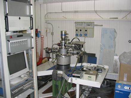
Fig. 8: The DEAR setup in the laboratory.
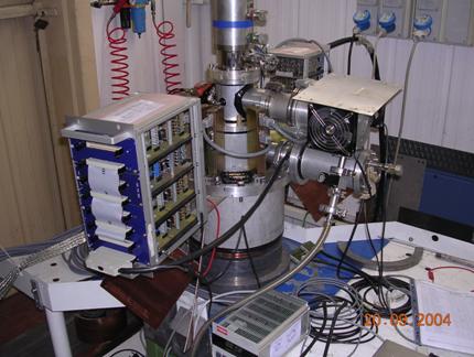
Fig. 9: The DEAR setup in the laboratory- detail.
The CCDs [45] resolution, as checked in April 2004, is reported in Table 2. One can easily see that CCDs are an almost ideal detector for the few keV X-rays.
Table 2: Check of the status of the 16 CCDs during a run test of April 2004 with a source in the laboratory.
The biggest modification to the setup is the replacement of the plastic vessel, which contained the target gas in the DEAR experiment, with a copper conductor that must be able to carry a large current close to the surface. At the moment we favor the following design: a spiral from a 3.50 m bent copper tube, 10 mm in diameter and with a wall thickness of 1 mm (fig. 10). A current of 50 A will be circulated in the spiral, which can be cooled by a closed demineralized water circuit.
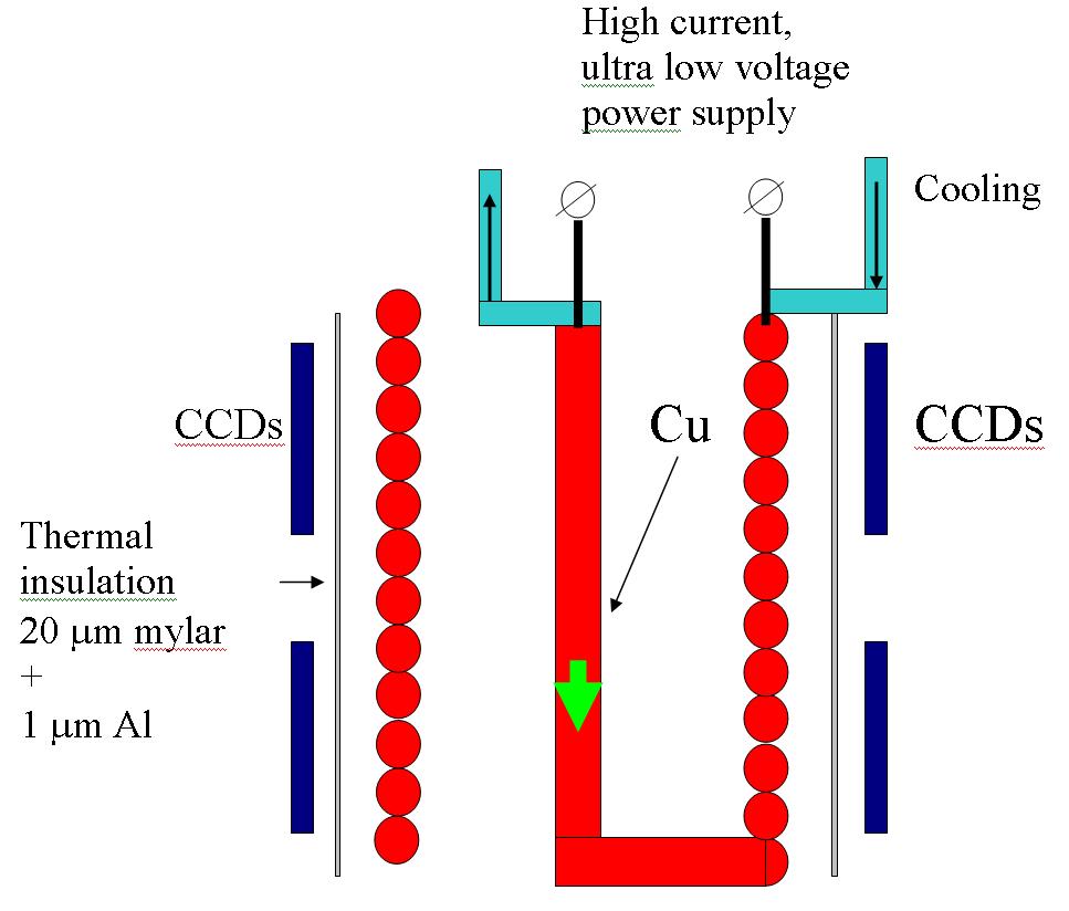
Fig. 10: The copper target used in VIP.
This solution should provide a uniform distribution of the surface current and, at the same time, a higher surface current density with respect to the copper bar à la Ramberg and Snow, thus optimizing the acceptance and the detection efficiency for the X-rays.
Fig. 11 shows the CCD system together with its ancillary systems (read-out electronics and cooling)
.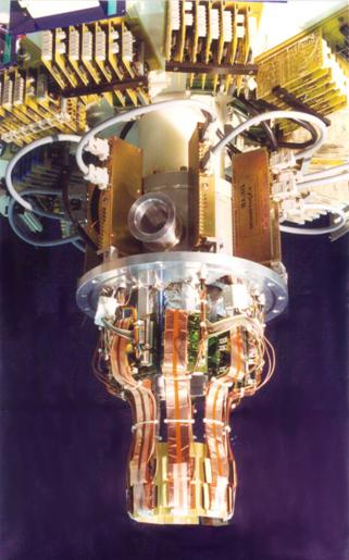
Fig. 11: The 16 CCD-55, together with the cryogenic and readout systems.
DAQ, slow control and monitoring
The read-out of the several million channels of the CCDs is accomplished through a very reliable DAQ system, honed by years of operation with DEAR, while a continuous monitoring will keep under control the relevant parameter needed to assure the good functioning of the VIP setup.
Examples of important quantities to be monitored are:
- the CCDs temperature, which should be stabilized at about 170 K in order to minimize the dark current and to obtain the best energy resolution;
- the insulation vacuum in order to allow for an efficient cooling and to prevent the formation of ice, which would decrease the CCD quantum efficiency and could possibly produce irreversible damages.
Moreover, there are few controls that should be implemented to talk to the experimental setup (vacuum pump, cryogenic compressor, DAQ electronics).
The DAQ, as well as the Slow Control and Monitoring, will be operated remotely through the WAN.
In what follows we describe our adopted solution, based on commercial hardware and software.
Slow Control and Monitoring Hardware
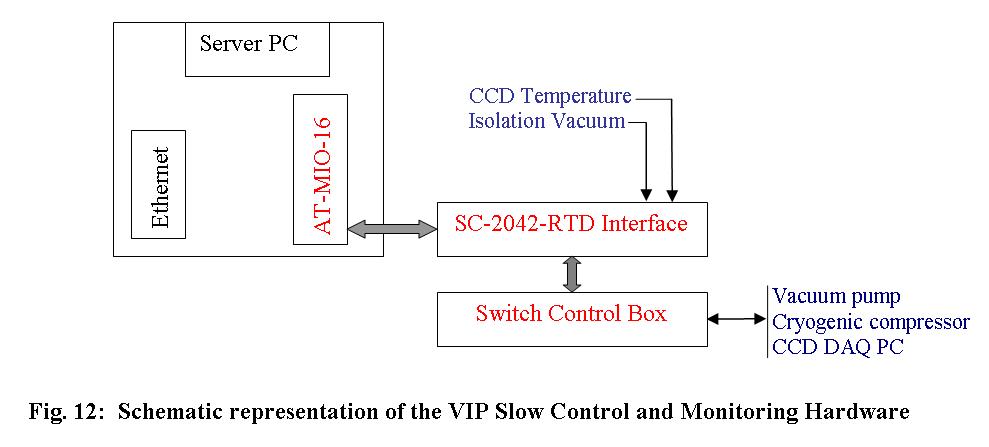
An IBM PC AT compatible computer will be installed in the experimental area expanded with a National Instruments AT-MIO-16L-9 multifunction Data Acquisition (DAQ) board. The AT-MIO-16L-9 contains a 12-bit ADC with up to 16 analog inputs, two 12-bit DACs with voltage outputs, eight lines of TTL-compatible digital I/O, and three 16-bit counter/timer channels for timing I/O.
The AT-MIO-16L-9 will be interfaced with a resistance temperature device (RTD) signal conditioning accessory for National Instruments DAQ boards, namely SC-2042-RTD. The SC-2042-RTD provides eight channels of current excitation (1 mA), and will allow the measurement of the voltages on the PT-100 thermoresistors mounted on the CCD mechanical support.
The temperature of the CCD chips will be calculated using a polynomial fit of the standard PT-100 voltage vs. temperature dependence.
The isolation vacuum pressure will be monitored using a Balzers IKR 050 vacuum gauge together with a Balzers vacuum measurement and control unit of the type TPG 300 or IMG 300 connected to one of the AT-MIO-16L-9 ADC channels.
Concerning the on/off switches, a custom made box, with logic-switched 220V relays and 0, 5V logic signals will be interfaced with the Digital I/O lines of the AT-MIO-16L-9 board.
A schematics of the Slow Control and Monitoring Hardware is shown in fig. 12.
Slow Control and Monitoring Software
The software will be based on National Instruments LabView graphical development environment and will consist in an graphical user interface (GUI) through which the user will be able to monitor and control the CCD temperature and isolation vacuum, the status of alarms related with each monitored quantity, the switches associated with any device connected to the switch control box.
The GUI will be fully remote controlled across the network using VNC software (Virtual Network Computing). Moreover, the variables monitored by the acquisition program will be published in real-time on the VIP WWW page in the form of an HTML report, through the help of LabView Internet Toolkit. The web reports will be available to any authorized member of the VIP experiment .
In case of hardware failures or out of range values for the CCD temperature or isolation vacuum pressure, an automatic GSM-SMS procedure is foreseen.
In fig.13 a schematic description of the remote communication with the Slow Control and Monitoring Server is presented.

Fig. 13: Remote Communication with the Slow Control and Monitoring software