ATLAS MDT HIGH VOLTAGE GENERATION AND DISTRIBUTION
G.Felici, M.C.Spitalieri, Laboratori Nazionali di Frascati dell’INFN, Frascati, Italy
A.Lanza, INFN Sezione di Pavia, Pavia, Italy
E.Petrolo, INFN Sezione di Roma, Roma , Italy
G.Passuello, S.Petrucci, CAEN, Viareggio, Italy
J.Huth, J.Oliver, Department of Physics Harvard University, Cambridge, Massachusetts
E.Hazen, Department of Physics Boston University, Boston, Massachusetts
P.M.Mockett, University of Washington, Seattle, Washington
Abstract
The high voltage generation and distribution system for the Atlas MDT chambers is described. A high modularity together with a high reliability is required to supply a detector with a large number of tubes (about 370000) for at least 10 years at LHC. Furthermore the capability to reverse the high voltage to cure aged tubes and to disconnect tubes with broken wires (using a fuse per tube) must be foreseen. The layout of the system proposed is based on three main components: the main high voltage generator; the boards for remote regulation, monitor and limiting of tension and current; the hedgehog cards for the distribution of the high voltage to each single MDT tube.
1. Introduction
The high voltage system for the Monitored Drift Tube (MDT) chambers has to be able to supply the 1200 chambers of the Atlas muon spectrometer.
The MDT chambers perform the precision coordinate measurement in the bending direction of the spectrometer, providing the momentum measurement. A safe and stable operation for 10 years in the high rate environment has to be guarantee.
A MDT chamber is made of two multilayers of high-pressure drift tubes assembled on a support frame. Each multilayer is composed of three or four layers (depending on the chamber) of closely spaced tubes. The number of tubes per layer ranges from 24 to 72 and their length from 1 to 6 m.
In order to achieve a stable space-time relation [1] an overall high voltage accuracy and stability less then 0.3% is required , together with a maximum operating voltage of 4 kV. Moreover, because of the large number of channels involved a high modularity is required; as a consequence the system has to be able to work properly also in case of tubes with broken wires. Lastly the capability to supply MDTs using high voltage with reversed polarity must be foreseen (this point is useful to cure aged tubes).
A crucial point for the HV power supply design is the maximum current that the system has to supply. For MDT chambers this value can be calculated according to the amount of integrated charge for 10 years at the nominal working conditions; this calculation gives an average dragged current of about 1.5 mA for the biggest chamber.
The proposed solution for the MDTs HV generation and distribution is composed of three parts:
In the following sections the main characteristics of each part are reported.

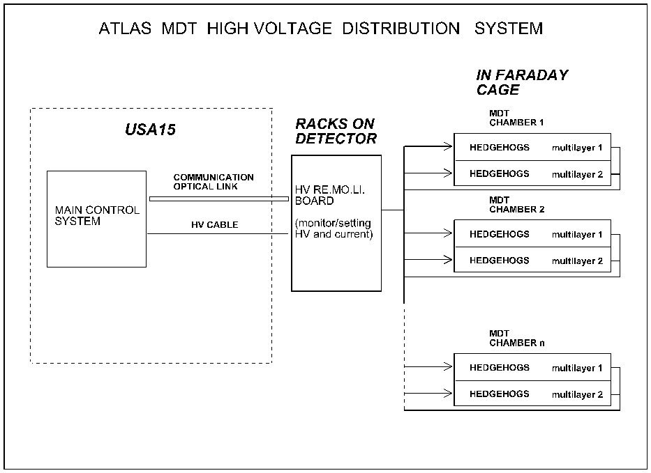
Fig.1 Block diagram of the proposed Atlas MDT high voltage system
2. Main Control system
The operation of the entire MDT high voltage system is carried out by the Main Control System, located in the control room USA15, that generates the high voltage and manages communications and controls.
A modular high voltage system is realised in order to host up the high density HV generation boards and to support the hardware and software communication. For the ATLAS spectrometer each HV generation board hosted in the system has to be provided with a local processor and 10 HV outputs to manage and supply RE.MO.LI. boards (see the following section). RE.MO.LI. board controls can be carried out either by an optical or an electrical line (in this case an optocoupler will be used to avoid ground loop [2]).
One main HV channel is foreseen to supply three chambers, so 40 HV generation boards housed in three crates localised in the USA15 control room will supply the full detector (about 1200 chambers). A block diagram of the whole system is shown in fig.1.
These boards, located in racks around the apparatus, have been designed to provide the REgulation, MOnitoring and LImiting of tension and current.
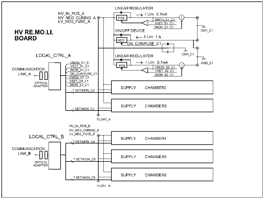
The single board (fig.2) is made of two identical sub-systems. Each sub-system supplies three chambers by means of six linear regulators individually adjustable from 0 to 4 kV.
Both tension and current of these channels are monitored; the current limit for each channel is hardware set to 0.7 mA. About 200 boards, located on racks around the apparatus, will be used to supply all MDT chambers.
A local controller, that communicates with the Main Control System through an optical line, manages the sub-system operations. The HV line that supplies each sub-system is also used to blow the fuse (in case of MDT with broken wire) and to cure aged tubes. A network made of passive components is used for the connection between the chamber and the RE.MO.LI. board ground in order to avoid ground loop.
 Fig.2 High voltage distribution board (RE.MO.LI. board)
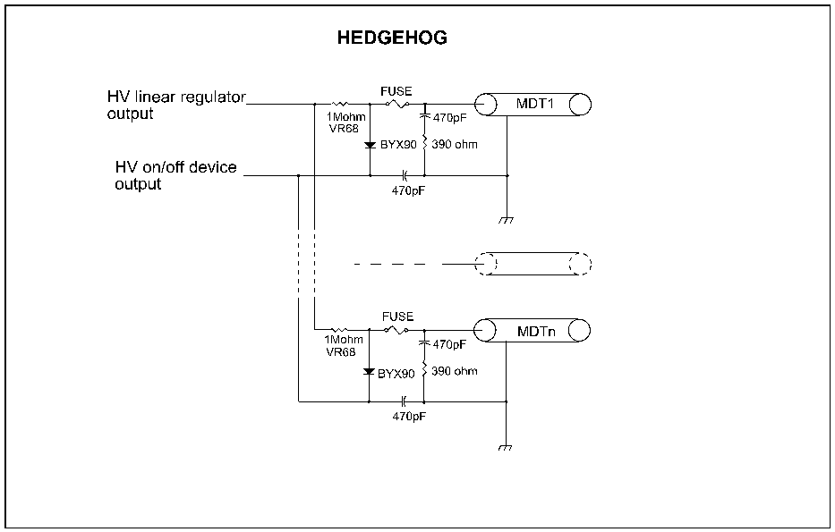
 Fig.3 Hedgehog card
These cards are connected directly to the tube endplugs and are used to distribute high voltage to the single MDT tube. A Faraday cage encloses all cards that are used to supply a chamber multilayer; three HV cables have to be connected for each chamber (two cables to supply HV to multilayers and one cable to bring out the diodes common chatode line for blowing fuse or MDT curing option purpose).
Fig.2 shows the circuit block diagram for three chambers voltage setting and voltage/current sensing (these circuits are located on the RE.MO.LI. boards) while the passive components located on the hedgehog cards are shown in fig.3.
Since we are using one linear regulator to supply high voltage to the single multilayer, one fuse per tube has been introduced [3] in order to avoid that a broken wire makes the whole multilayer useless. The burning of the fuse relative to the MDT with the broken wire is obtained through a diodes network; this network is also used to apply reversed voltage to the chamber (curing option).
The 470 pF capacitors (used to shunt diodes parasitic capacitance to ground) and the termination network (470 pF/ 390 W ) for the signal on the HV side are also shown. A 1 MW – 0.5 W high voltage resistor is used as limiting resistor; the current is hardware limited by the linear regulator to 0.7 mA.
5. system operation
Three different system conditions are foreseen.
5.1 Normal operation
In this condition (figg.2-3) the positive high voltage applied to the linear regulator is also applied, through the forward biased protection diode of the ON/OFF device, to the hedgehog common chatode diodes (a drop of about 200 V on the linear regulator makes these diodes reversed biased).
5.1 Fuse Blow option
The main HV generator, located in the USA15, relative to the chamber with the broken wire must be turned off, the HV cable has to be connected to a negative low voltage high current (1A) generator and the RE.MO.LI. ON/OFF device must be enabled. In this condition only a very small current flows through the linear regulator protection diode due to the 1 MW high voltage series limiting resistor, while most of the current flows through the ON/OFF device and the hedgehog diode connected to the broken wire. This current blows the fuse, disconnecting the relative tube.
5.3 Curing option
In this case (see Fuse Blow option) the high voltage cable relative to the chamber to be cured, has to be disconnected from the main HV generator and connected to a negative high voltage power supply. This generator has to provide an adjustable high voltage from 0 to 3 kV and a maximum current of 30 mA. Both current and tension can be monitored. The diodes polarisation, during the curing option, is the same of the Fuse Blow option, while the maximum dragged current is limited to 30 mA.
6. conclusion
The proposed system satisfies all the ATLAS muon spectrometer requirements, providing a safe and stable operation for MDT chambers. During the normal operation, the system is completely controlled by the Detector Control System (DCS). Manual operation is required only few times to disconnect the main generator for the fuse/curing option (remote control of this operation is possible, but too expensive, so at the moment, it is not foreseen).
7. References
[1] ATLAS Collaboration, ATLAS Muon Spectrometer Technical Design Report, CERN/LHC/97-22 ATLAS TDR 10
[2] J.Huth and J.Oliver, Atlas Muon Grounding, ATLAS internal note MUON-NO-218
[3] P.Mockett, Design and Test Results for a Proposed MDT Fuse System, ATLAS internal note MUON-NO-228